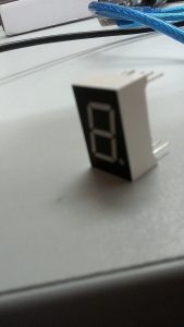
Everyone has one in their house, a clock on your VCR you never set, a timer on your cooker or your microwave, a digital clock. The seven segments of LEDs that light up to form numbers are made up of Seven Segment Displays.
There are all sorts of projects you might want to add these to, but this is a basic introduction with one number.
The pins on these displays may differ, on mine, the first pin did nothing and the middle pin on the top and bottom connected to ground. Each of the other pins was a positive for a different segment on the display.
First things first, look up the data sheet of your display and figure out how much current and voltage it should take, no point burning it out. You will probably need to hook up a resister for safety.
I’m using an Arduino Mega, but you could do it with any Arduino boards or a Raspberry Pi.
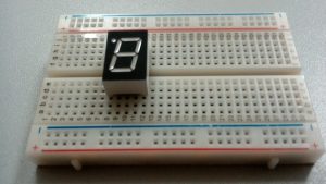
Put the display in a breadboard so each pin can be powered separately and first wire up the ground with a resister, then connect it to the Arduino ground.
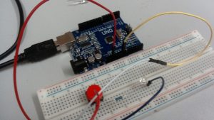
Then, connect a jumper line to the 3.5V on the Arduino and connect it to each pin on the Display in turn. If everything works, each segment should light up as you power it up.
To make it more interesting, wire up each segment to a digital pin on the board. For Arduino, I used pins 1-7, which is a bit interesting.
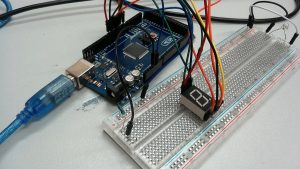
Firstly, you can’t connect pin 0 or pin 1 to anything while the sketch is uploading to the board. Once the program is uploaded, you can then connect these pins.
I used pins 1-7, and connected them to the display, skipping the ground pins.
The below code has 2 parts, and is derived from the blink program.
// the setup function runs once when you press reset or power the board
void setup() {
pinMode(7, OUTPUT);
pinMode(6, OUTPUT);
pinMode(5, OUTPUT);
pinMode(4, OUTPUT);
pinMode(3, OUTPUT);
pinMode(2, OUTPUT);
pinMode(1, OUTPUT);
// for each pin we want to use, we need to set it to output.
}
// the loop function runs over and over again forever
void loop() {
digitalWrite(7, HIGH); // turn on whatever segment is connected to pin 7
digitalWrite(6, LOW); // turn off whatever segment is connected to pin 6
digitalWrite(5, HIGH);
digitalWrite(4, LOW);
digitalWrite(3, HIGH);
digitalWrite(2, LOW);
digitalWrite(2, HIGH);
delay(4000); // wait for a 4 seconds
digitalWrite(7, LOW); // now whichever segment is connected to pin 7 will turn off
digitalWrite(6, HIGH); // now whichever segment is connected to 6 will turn on
digitalWrite(5, LOW);
digitalWrite(4, HIGH);
digitalWrite(3, LOW);
digitalWrite(2, HIGH);
digitalWrite(1, LOW);
delay(4000); // wait for 4 seconds
}
The display is really simple, it is made up of seven LEDs and you can turn on and off each part at the same time to from numbers. This is a basic introduction, you can add more displays for more advanced features.
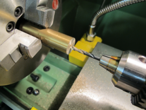 The cooker door wouldn’t snap closed properly. A quick disassembly of the hinges showed that a brass disc had a flat spot from years of wear and tear. Replacements were no longer available. Time to make some new ones on the lathe.


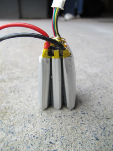 Lithium batteries are
 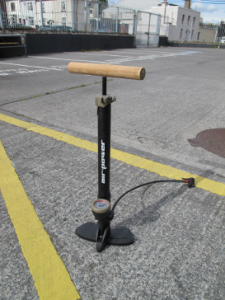 Well not quite, but a wooden handle anyway. We don’t just do bits and bytes at TOG! The bicycle pump handle broke and it seemed a shame to dump an otherwise perfectly good pump. So with a bit of nice round wood cut from an old roller blind pole, we made a new handle. Drilled a hole in the handle and a couple of small holes in the metal shaft of the piston to give the glue a bit of grip.
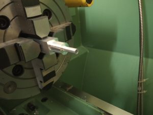 was made from aluminium, a coupling for connecting two pieces of
  unctional and looks a lot better!