This project is by our member Jeffrey Roe and is about saying goodbye to the default firmware on this smart plug.
The project started with a request from an artist for a device to turn on/off up to eight devices that are mains powered with a custom timing sequence. I decided to try out smart plugs as they have come down in price. It would also save building a circuit of relays as I have done in the past. Most smart plugs come with a firmware that connects the device to a private server and requires the internet to control it. The use case called for this unit to be used without the internet.
After doing a bit of research, the open firmware Tasmota seemed to have all the features the project needed and would cut down on the need to code up something totally from scratch. To flash the new firmware, some devices allow this to be done wireless but most require soldering wires to the microcontroller. The ease of soldering the wires varies from device to device due to the placement of the chip. The soldering job can be much harder on some devices.
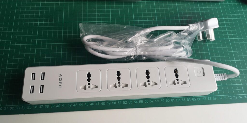
Wireless flashing seemed the easy way to go as it required no soldering, so I purchased two plugs that the internet said worked with the TUYA-CONVERT. I went for two AOFO 4AC + 4USB Power Strip plugs ( Model C379 ).
This is when the problems started. After hours of work, getting PI ready, installing the flashing tool and nothing happens. It turns out the blog post that recommended this plug combination with using the flashing tool had a comment at the end of the post (Which I did not read before starting out). It warned people that a recent update by the manufacturer fixed the hole that allowed users to flash a new firmware over the air.
Plan B was now in operation and I knew a soldering iron would be involved. https://templates.blakadder.com/index.html is a great website with a list of devices that can be used with Tasmota, which pins to connect to, how to get access to the pins and the template to control all the features Unfortunately the two plugs I now had awkwardly required the chip to be completely removed in order to flash them.
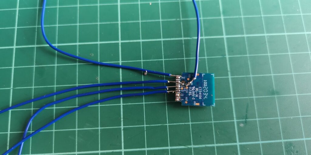
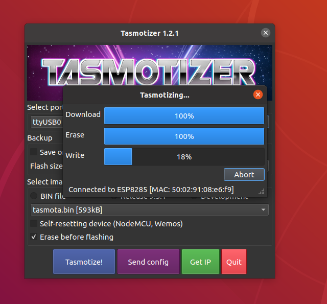
Due to lockdown, all I had at home was a soldering iron, solder and solder braid. No desoldering tools. After some effort, I managed to desolder the chip and connect the five wires required to flash the chip. Using the great tool Tasmotizer, it is straightforward to flash the chip with the wires in place. You can even give the WiFi details and config template.
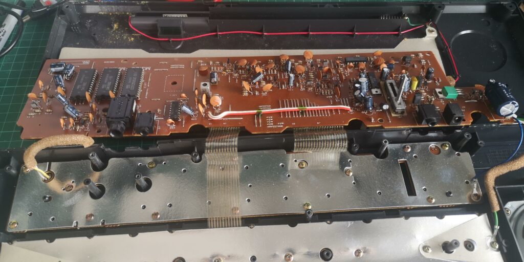
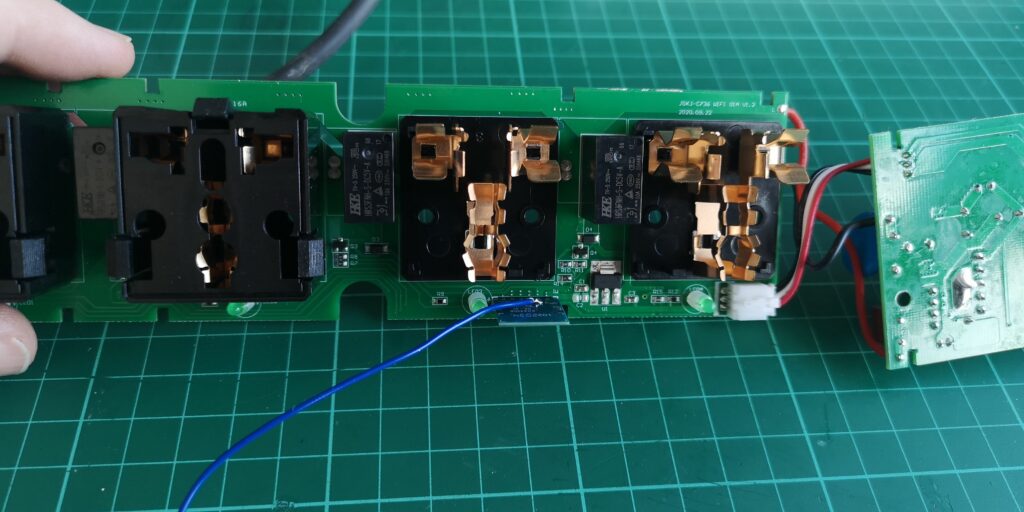
Then started the job of putting the chip back in the board, soldering it again and putting all the parts back together. With a quick test, all was back working but another plug was still left one to do. In the previous photo above, you might have noticed a black plastic cover on the board that covers each plug. That cover blocks access to a pin required to put the chip into flashing mode and hence the need for all this desoldering. The second time around I checked if I could remove this cover and to my surprise, it came off.
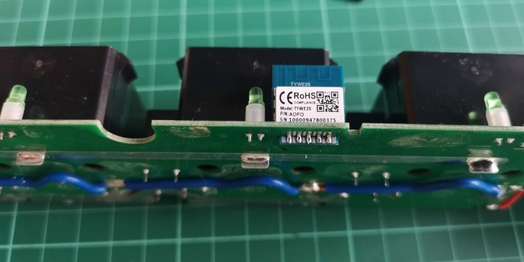
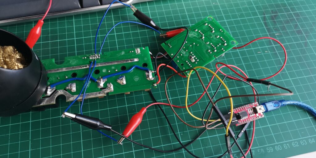
\o/. With the cover off I could just solder wires to all the pins and not remove the chip from the board. This speeded up the whole process and made flashing the chip much much easier. A few crocodile clips, an FTDI programmer and we were in business. Both plugs are now ready to be controlled via WiFi API call.
I have updated the page on https://templates.blakadder.com/aofo_C379.html so anyone else flashing these plugs can know about this shortcut.
The rest of the project involved adventures in writing code for esp32 & esp8266 and problems with WiFi but that is for another time.
If you would like to see more photos from the project check out our gallery.